

In optical systems, filters are key components for precise spectral control. Yet one often overlooked but critical trait is their performance stability amid temperature fluctuations—known as “temperature drift”. Understanding and quantifying this drift is essential for designing high-precision, high-reliability optical systems. Below is a systematic breakdown of filter temperature drift, including its manifestations, underlying mechanisms, influencing factors, core substrate materials, and impacts across different application environments.
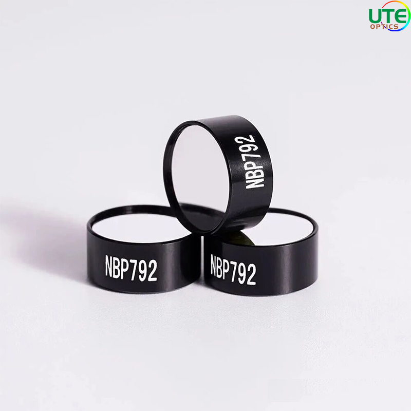
I. What Is Filter Temperature Drift?
Filter temperature drift primarily describes the phenomenon where core spectral parameters—such as center wavelength, cut-off wavelength, and bandwidth—shift with environmental temperature changes. For most filter types, this drift mainly appears as a shift in the center wavelength (either toward longwave or shortwave).
Typical Behavior: For common bandpass filters, rising temperatures usually push the center wavelength toward the longwave (red) direction; falling temperatures shift it toward the shortwave (blue) direction. This shift is often linear and can be defined by a coefficient within a specific temperature range.
- Key Parameter**: Center wavelength drift coefficient (unit: nm/°C). For example, a filter with a drift coefficient of +0.02 nm/°C means its center wavelength shifts 0.02 nm longwave for every 1°C temperature increase.
II. Underlying Mechanisms & Influencing Factors of Temperature Drift
Temperature drift is not caused by a single factor; it depends on the thermophysical properties of the filter’s substrate and its complex multilayer thin-film structure.
1. Core Physical Mechanisms
- Thermal Expansion Effect: Temperature changes directly trigger thermal expansion of the filter’s substrate and thin-film materials. Increased substrate thickness (d) alters the optical path, leading to spectral wavelength shifts.
- Thermo-Optic Effect: Temperature changes modify the material’s refractive index (n). For thin-film interference filters—whose operation relies on light interference at multilayer interfaces—optical thickness (n×d) is the key parameter determining interference conditions.
Thus, the center wavelength (λ) drift of a filter is mainly governed by the thermal stability of its optical thickness (OT = n×d). Its temperature sensitivity can be approximated as:
Δλ/λ ≈ (Δn/n + Δd/d) × ΔT
Where:
- Δn/n = Temperature coefficient of refractive index (thermo-optic coefficient)
- Δd/d = Linear thermal expansion coefficient
2. Main Influencing Factors
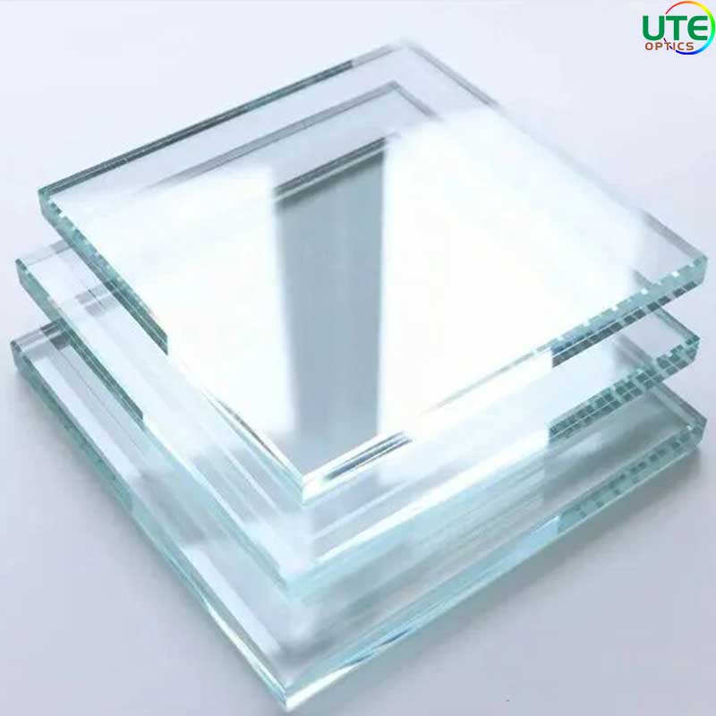
a) Substrate Materials
The substrate is the filter’s carrier, and its thermal expansion coefficient is the primary factor affecting drift.
- Optical Glass (e.g., BK7, B270): Has a relatively high thermal expansion coefficient (~7–8 × 10⁻⁶ °C⁻¹). Filters using this substrate typically have larger drift, with coefficients ranging from +0.02 to +0.04 nm/°C.
- Fused Silica: Features an extremely low thermal expansion coefficient (~0.55 × 10⁻⁶ °C⁻¹), making it ideal for low-drift filters. Drift coefficients for fused silica substrates range from +0.001 to +0.01 nm/°C.
- Crystal Materials (e.g., CaF₂, Ge): Widely used in mid-infrared applications, these materials have unique thermo-optic and expansion coefficients that require case-by-case evaluation.
b) Thin-Film Materials & Film Stack Design
The thermo-optic coefficient (dn/dT) of coating materials varies significantly and is another decisive factor.
- Common Oxide Films (e.g., TiO₂, Ta₂O₅, SiO₂): High-refractive-index materials like TiO₂ and Ta₂O₅ have large positive thermo-optic coefficients (dn/dT > 0)—the main cause of filter center wavelength “red shifts”. SiO₂ (low-refractive-index material) has a smaller (even negative) thermo-optic coefficient, allowing partial drift compensation via careful film stack design (e.g., using SiO₂ to offset Ta₂O₅’s positive effect).
- Soft vs. Hard Films: Hard films (via physical vapor deposition, PVD) have denser structures and more consistent thermal performance. Soft films (e.g., some chemically deposited films) may exhibit unstable thermal behavior due to their porous structure.
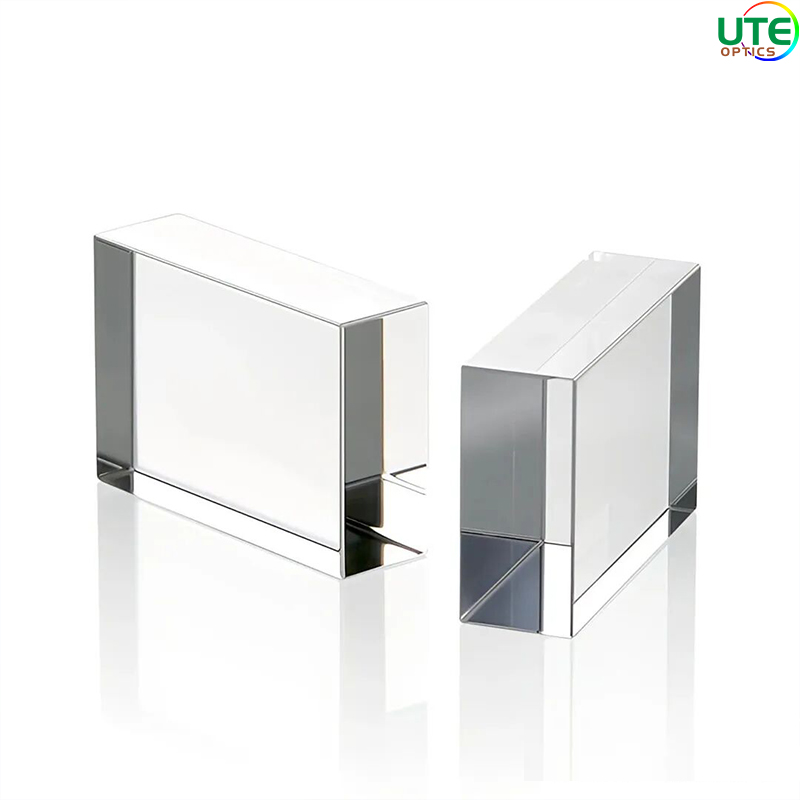
c) Filter Types
- Bandpass Filters (Interference Type): Most sensitive to temperature, as their passband depends on precise optical thickness interference.
- Longpass/Shortpass Filters: Their cut-off wavelengths drift, but the impact is less critical than on bandpass filters’ core passbands.
- Absorption Filters (e.g., Colored Glass): Spectral traits depend on material absorption; temperature drift is usually small. However, high temperatures may cause irreversible chemical changes, altering the spectrum.
III. Considerations & Challenges Across Application Environments
The impact of temperature drift varies with the harshness of the application environment.
- Room-Temperature Laboratory Environments (15–30°C):
Drift is negligible for wide-bandwidth filters (>10 nm, typically). For narrowband filters (e.g., 1 nm bandwidth), a 15°C temperature swing can cause 0.3 nm drift—30% of the bandwidth—leading to significant signal attenuation.
- Outdoor/Industrial Environments (-20°C to +50°C or wider):
This is where temperature drift is most problematic. Examples include:
- Fluorescence Microscopy: Precise wavelength matching is required for excitation/emission. A 70°C swing (e.g., -20°C to +50°C) could cause >1.4 nm drift (at 0.02 nm/°C), reducing excitation efficiency or emission signal collection and lowering image contrast.
- Spectrometers: Drift in calibration/spectral filters causes direct wavelength calibration errors.
- Environmental Monitoring/LiDAR**: These outdoor systems use ultra-narrowband atomic/molecular absorption filters (e.g., iodine filters for wind measurement) with picometer-level bandwidths. Even tiny drift is fatal, requiring strict temperature control.
High-Power Light Source Systems:
Filters absorb light energy and generate heat, causing “thermal lens” effects and local temperature rises—even with stable ambient temperatures. This leads to center wavelength drift.
Aerospace & Defense:
Operating temperatures range extremely wide (-55°C to +85°C) with strict reliability demands. Solutions include using “ultra-low-drift filters” (fused silica substrates + custom film stacks) or integrating thermoelectric coolers (TECs) for active temperature control (stabilizing at ~25°C).
IV. How to Address & Quantify Temperature Drift
1. Mitigation Strategies
Material Selection: Prioritize fused silica for substrates; choose coating materials with well-matched thermo-optic coefficients.
Active Temperature Control: For high-demand applications, mount the filter in a temperature-controlled holder with a TEC and temperature sensor—this is the most reliable method.
System-Level Compensation: Use software algorithms to reverse-compensate wavelength readings based on measured temperatures.
2. Quantification & Testing
Responsible manufacturers clearly specify filter temperature drift coefficients in datasheets. This data is typically obtained via spectral testing in a high-low temperature chamber. Users must prioritize this parameter during selection.
Industry Reference Data (Non-Extreme Values):
- Standard filters (BK7 substrate): ~+0.02 ± 0.01 nm/°C
- Low-drift filters (fused silica substrate): ~+0.005 ± 0.003 nm/°C
- Ultra-low-drift/temperature-controlled filters: TEC stabilization (±0.1°C) achieves wavelength stability <±0.001 nm
Conclusion
Filter temperature drift is an inevitable phenomenon driven by material physics. Deep understanding and quantification are foundational to building high-stability optical systems. However, temperature drift is just one of the filter’s many critical performance metrics. During selection and design, it must be balanced with other indicators: passband transmittance, cut-off depth, waveform factor, angular characteristics, power tolerance, and environmental durability.
Ultimately, a successful filter solution requires comprehensive analysis and customization—based on the user’s specific spectral needs, coating process capabilities, and end-use environment (temperature range, mechanical stress, chemical exposure, etc.). Managing temperature drift within the broader context of optical system engineering—rather than in isolation—ensures optimal performance and reliability from design to deployment.